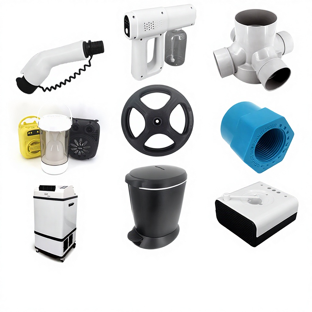
Respuesta rápida: Moldeado por sobremoldeo frente a moldeado de dos fases
Utiliza el sobremoldeado por inserción cuando el volumen sea moderado, el sustrato pueda introducirse en el molde o se necesite flexibilidad durante la validación. Utiliza el moldeo de dos inyecciones cuando el volumen sea lo suficientemente elevado como para justificar un utillaje más complejo y el proyecto requiera una unión repetible, una mayor eficiencia del ciclo y un posicionamiento más preciso entre los materiales. El proceso adecuado depende del volumen anual, del material del sustrato, de los requisitos de adhesión, de la tolerancia, del aspecto estético y de si el material blando se utiliza para proporcionar agarre, sellado, control de vibraciones o protección contra impactos.
Modos habituales de fallo en el sobremoldeado
| Problema | Causa probable | Solución de diseño o de proceso |
|---|---|---|
| Falta de vínculo afectivo | Familia de TPE incorrecta, sustrato contaminado o temperatura de fusión baja. | Utiliza grados compatibles, una manipulación limpia, una temperatura de interfaz más alta o bloqueos mecánicos. |
| Destello al apagarse | Presión del material blando, acero de cierre deficiente o mala colocación de las piezas. | Mejorar los ángulos de cierre, añadir características de localización y controlar la presión de inyección. |
| Deslaminación tras el envejecimiento | Exposición a sustancias químicas, calor, humedad o energía superficial incompatible. | Realizar pruebas de envejecimiento y validar la combinación exacta de materiales de producción. |
| Marcas de flujo de carácter estético | Ubicación de la compuerta, capa fina y blanda, baja temperatura o aire atrapado. | Comprueba la posición de la boquilla, la ventilación, el espesor de la pared y la temperatura de la masa fundida. |
Pruebas y validación antes de la producción
No apruebes una pieza sobremoldeada basándote únicamente en su aspecto. En el caso de empuñaduras funcionales, juntas, cubiertas o elementos de control de vibraciones, solicita un plan de validación sencillo que incluya comprobaciones de la adhesión, inspección dimensional y envejecimiento en condiciones reales. Las pruebas de desprendimiento o de adhesión pueden basarse en métodos como ASTM D903, aunque los ensayos personalizados de tracción, par o compresión pueden resultar más adecuados para la geometría real de la pieza.
Para controlar los riesgos desde el punto de vista del comprador, pida al proveedor que moldee piezas de muestra utilizando el sustrato de producción previsto y el tipo de TPE correspondiente, y no solo placas de laboratorio genéricas. Una unión que funcione en una tira de prueba puede fallar en un sustrato moldeado texturizado, reforzado con fibra de vidrio o contaminado.
El sobremoldeado —el proceso de moldear un material sobre otro o a su alrededor— se ha convertido en una de las técnicas más potentes en el diseño de piezas de plástico, ya que permite a los ingenieros combinar sustratos estructurales rígidos con empuñaduras de tacto suave, crear juntas integradas, encapsular componentes electrónicos y producir componentes estéticos multicolores en una única célula de fabricación. El mercado mundial del sobremoldeado, valorado en $12.3 mil millones en 2023, sigue creciendo a una tasa compuesta anual (CAGR) del 6,8%, a medida que los diseñadores de productos buscan reducir los pasos de montaje, disminuir el número de piezas y mejorar la experiencia del usuario mediante la integración de múltiples materiales. Desde mangos de dispositivos médicos con empuñaduras de TPE antimicrobiano hasta carcasas de sensores para automóviles con juntas de silicona moldeadas, el sobremoldeado elimina las operaciones de montaje secundarias y crea uniones que pueden superar la resistencia de cualquiera de los materiales por separado.

Esta guía exhaustiva abarca los dos métodos fundamentales de sobremoldeo —el moldeo de dos inyecciones (o de múltiples inyecciones) y el sobremoldeo con inserto—, junto con los aspectos científicos de la compatibilidad de materiales, la ingeniería de la resistencia de la unión, las normas de diseño y las recomendaciones específicas para cada aplicación. Tanto si se trata de sobremoldear un agarre blando de TPE sobre el mango de una herramienta eléctrica de polipropileno como de encapsular una placa de circuito impreso con termoplástico para impermeabilizarla, las decisiones de diseño que se tomen en el modelo CAD determinan directamente si la unión se mantendrá durante toda la vida útil del producto o si se deslaminará en cuestión de semanas. Comprender la química de los polímeros en la unión, los requisitos térmicos del proceso y los factores geométricos de diseño que favorecen la adhesión es esencial para el éxito en el diseño de piezas multimaterial.
Moldeo por dos inyecciones frente a sobremoldeo por inserción: cómo elegir el proceso adecuado
Aunque ambos métodos permiten fabricar piezas con varios materiales, el moldeo de dos inyecciones (o de múltiples inyecciones) y el sobremoldeo con inserto difieren fundamentalmente en cuanto al flujo del proceso, los requisitos de equipamiento y la viabilidad económica en función de los distintos volúmenes de producción.
Moldeo de dos inyecciones (multiinyección): En el moldeo de dos inyecciones, el sustrato (primera inyección) se inyecta en una cavidad de un molde giratorio o deslizante; a continuación, el molde se desplaza a una segunda estación, donde el material de sobremoldeo (segunda inyección) se inyecta directamente sobre el sustrato, que aún está caliente. Todo el ciclo se completa en una sola prensa con una máquina de moldeo por inyección de dos inyecciones especializada, equipada con dos unidades de inyección independientes. La ventaja fundamental es que el sustrato nunca sale del molde entre inyecciones, permaneciendo a una temperatura de entre 80 y 120 °C cuando se inyecta el segundo material; esta temperatura elevada favorece la unión química y la interdifusión en la interfaz entre los materiales. Los tiempos de ciclo suelen oscilar entre 35 y 60 segundos para ambas inyecciones combinadas. El moldeo de dos inyecciones requiere una mayor inversión en utillaje ($60 000-150 000 para el juego completo de moldes frente a $25,000-60 000 para un molde de una sola inyección), pero elimina toda la manipulación manual, lo que lo convierte en la opción preferida para volúmenes superiores a 100 000 piezas al año, en los que el ahorro en mano de obra amortiza el sobrecoste del utillaje en un plazo de 12 a 18 meses.
Sobremoldeo de insertos: En el sobremoldeado por inserción, el sustrato se moldea por separado como una pieza estándar de una sola inyección y, a continuación, se coloca —ya sea manualmente o mediante un robot— en un segundo molde, donde se inyecta el material de sobremoldeado a su alrededor. El sustrato se encuentra a temperatura ambiente cuando se introduce el material de sobremoldeo, lo que reduce la fuerza motriz térmica necesaria para la unión química. Para compensarlo, el sobremoldeo por inserción suele emplear temperaturas de fusión más elevadas (entre 20 y 30 °C por encima de las habituales en el procesamiento estándar) y se basa en mayor medida en elementos de enclavamiento mecánico. El sobremoldeo con inserto es la opción económicamente más adecuada para volúmenes inferiores a 50 000 piezas al año, para piezas en las que el sustrato es metálico (que no pueden moldearse en dos inyecciones) y para aplicaciones en las que el sustrato requiere operaciones posteriores al moldeo (mecanizado, recocido, tratamiento superficial) antes del sobremoldeo. El coste de mano de obra para la carga manual de insertos oscila entre $0,08 y 0,25 por pieza, dependiendo de la complejidad de la pieza y de las tarifas laborales locales.
Compatibilidad de materiales: la química de las uniones en el sobremoldeado
El éxito de una aplicación de sobremoldeo depende de la compatibilidad entre el sustrato y el sobremoldeado. La compatibilidad viene determinada por tres factores: la similitud química (proximidad de los parámetros de solubilidad), la coincidencia de la energía superficial y el solapamiento de los rangos de procesamiento térmico.
La regla fundamental: Los materiales con parámetros de solubilidad similares se unen entre sí, mientras que los que tienen parámetros diferentes requieren uniones mecánicas. El parámetro de solubilidad de Hildebrand (δ) ofrece una medida cuantitativa: los materiales cuyos valores se sitúan entre 1,0 y 1,5 (MPa)^(1/2) suelen formar enlaces químicos aceptables. Las combinaciones de materiales más fiables en el sobremoldeado industrial son:
| Material del sustrato | Materiales compatibles para el sobremoldeado | Tipo de bono | Resistencia típica al desprendimiento (N/mm) |
|---|---|---|---|
| PP (polipropileno) | TPE-V (Santoprene), TPE-S (SEBS), TPO a base de PP | Químico (fusión por fusión) | 4.0-8.5 |
| PC/ABS | TPU (a base de poliéster), TPE-U, TPU a base de PC | Químico + Mecánico | 5.0-12.0 |
| PA6 / PA66 (nailon) | TPE-A (PEBA), TPU (a base de poliéter) | Química (enlaces de hidrógeno) | 6.0-15.0 |
| PBT (polibutileno tereftalato) | TPE-E (similar al COPE, como el Hytrel), TPU | Químico + Mecánico | 3.5-9.0 |
| ABS | TPU, TPE-S, TPE-U | Semi-chemical (solvent-like interface) | 3.0-7.5 |
Critical compatibility warnings: PP and PE are among the most challenging substrates due to their non-polar, low-surface-energy nature (surface energy ~29-31 mN/m vs. 42-46 mN/m for polar polymers). Overmolding onto PP or PE without mechanical interlocks or surface treatment (flame, plasma, or corona treatment to 38+ mN/m) will result in near-zero chemical bond strength. Nylon, conversely, offers excellent overmolding compatibility due to its polar amide groups — but its moisture absorption means that dry-as-molded nylon and conditioned nylon present very different surface energies, and overmolding onto moisture-conditioned nylon typically produces bonds 15-25% weaker than overmolding onto dry nylon. PC and PC/ABS substrates benefit from partial dissolution at the interface when overmolded with TPU, creating a solvent-weld-like bond zone 5-20µm deep.
Bond Strength Engineering and Design Factors
Overmolding bond strength is not a single material property — it’s a system-level outcome determined by material choice, processing parameters, and geometric design. Understanding how each factor contributes enables engineers to design bonds that meet functional requirements without over-engineering cost.
Processing Parameters: Melt temperature of the overmold material is the single most influential process variable. Increasing overmold melt temperature by 10-15°C typically improves bond strength by 15-25% by reducing melt viscosity at the interface (enabling better wetting) and providing more thermal energy to soften the substrate surface. Injection speed affects bond formation through shear heating at the interface — higher speeds (200-400 mm/s vs. 50-100 mm/s) generate frictional heat that can raise the interface temperature by 10-20°C locally. Pack pressure ensures intimate contact between materials during solidification; insufficient pack pressure (< 50% of injection pressure) results in micro-gaps at the interface, reducing effective bond area by 10-30%. For two-shot molding, the delay time between first and second shot is critical: 5-15 seconds typically produces optimal bond strength as the substrate skin is still above its glass transition temperature but the part is geometrically stable.
Geometric Design Factors: Chemical bonds provide baseline adhesion, but mechanical interlocks are the insurance policy. A well-designed overmolding interface incorporates undercuts, through-holes, or dovetail grooves that create a physical lock regardless of chemical compatibility. Through-holes in the substrate, filled by the overmold material, create rivet-like mechanical fasteners with pull-out strength of 50-200 N per hole (for 3-5mm diameter holes in 2-3mm thick substrates). Continuous dovetail grooves (60° included angle, depth 30-50% of substrate wall thickness) resist peel forces more effectively than straight-walled grooves. The bond line area itself should be maximized within geometric constraints — a common failure mode is designing a bond area that is adequate on paper but fails because stress concentrates at the perimeter edge, where peel initiates. As a rule of thumb, multiply your calculated bond area requirement by 1.5-2.0× to account for stress concentration effects at edges and corners.
Design Rules for Successful Overmolding
- Overmold wall thickness: 40-60% of substrate thickness, minimum 0.8mm: The overmold layer should be thick enough to fill completely without short shots but thin enough to avoid differential shrinkage that causes warpage. For TPE overmold on rigid substrates, 1.0-2.5mm thickness provides optimal tactile feel. Below 0.8mm, flow length is severely limited (maximum 30-40mm from gate).
- Include mechanical interlocks even when chemical bonding is expected: A 0.5-1.0mm deep undercut per side, through-holes at 30-50mm spacing, or a continuous groove with 45-60° dovetail angle provides redundant mechanical retention. This adds $500-1,000 to tooling cost but prevents field failures that cost 50-100× more. For safety-critical applications (medical, automotive), mechanical interlocks are mandatory regardless of chemical compatibility claims.
- Transition zones between substrate and overmold should use 30-45° ramps: Abrupt thickness transitions at the overmold edge create stress concentrations and provide a peel initiation site. A 30-45° ramp transition over 2-3mm spreads peel stress over a larger area and reduces the risk of delamination starting at the edge. For cosmetic overmolding, feather edges below 0.3mm thickness should be avoided as they result in incomplete filling and poor edge definition.
- Gate the overmold to flow from thick to thin sections across the bond interface: The overmold melt should flow parallel to the bond interface, not perpendicular toward it. Flowing parallel promotes shear heating at the interface and distributes material evenly before it contacts the substrate. Gating directly onto the substrate surface (perpendicular flow) creates localized hot spots and can erode the substrate surface, reducing bond quality.
- Keep substrate surface clean and dry — oil, mold release, and moisture destroy bonds: Mold release agents (silicone-based or wax-based) applied to the substrate mold transfer to the part surface, reducing surface energy by 40-60% and effectively acting as bond-line contaminants. Use external mold release only on the substrate tool’s ejector half where it won’t contact the overmold interface. For insert overmolding, specify clean-room handling or IPA wipe within 2 hours of overmolding for critical bonds.
- Validate bond strength with peel testing per ISO 813 or ASTM D903: A 90° or 180° peel test on a 25mm wide specimen provides the most reliable measure of overmold adhesion. Minimum acceptable peel strength varies by application: consumer products > 2.0 N/mm, industrial > 3.5 N/mm, automotive > 5.0 N/mm, medical > 6.0 N/mm. Test at both 23°C and the application temperature extremes (typically -20°C and +60°C) — TPE bonds often lose 40-60% of room-temperature peel strength at 60°C.
Matriz de aplicaciones industriales
| Solicitud | Substrate / Overmold | Proceso | Requisito clave |
|---|---|---|---|
| Power tool soft-grip handle | PA66-GF30 / TPE-S (SEBS, Shore A 55-70) | Two-shot, 50s cycle | Peel > 4 N/mm; chemical resistance to oils |
| Medical device overmolded seal | PC / TPE-U (medical grade, USP Class VI) | Insert overmolding, manual load | IP67 seal integrity; biocompatibility |
| Automotive sensor encapsulation | PCB + Connector / PA66-GF30 or PBT | Insert overmolding, robotic load | Vibration resistance 20G; -40 to 125°C |
| Consumer toothbrush handle | PP / TPE-V (Santoprene, Shore A 40-60) | Two-shot, 35s cycle | No delamination after 500 dishwasher cycles |
Marco de decisión sobre costes
Determining the most cost-effective overmolding approach:
The economic breakpoint between insert overmolding and two-shot molding is typically 50,000-100,000 parts per year. Below 50k: insert overmolding with manual loading, $25,000-60,000 tooling, $0.08-0.25 labor/part. Above 100k: two-shot molding, $60,000-150,000 tooling, $0.00 labor/part (fully automated). The crossover point where two-shot’s automated savings repay the additional tooling investment is approximately 18 months at 100k/yr volume. A hidden cost: insert overmolding yields 2-5% scrap from misloaded inserts vs. < 1% for two-shot. For the substrate material, design for the minimum wall thickness that meets structural requirements — reducing substrate thickness from 3.0mm to 2.0mm saves 33% on material cost and 15-20% on cycle time (cooling time scales with thickness squared). Overmold material cost is typically $4-8/kg for TPE grades — minimize overmold coverage to functional zones rather than fully wrapping parts for aesthetic-only coverage.
Common Troubleshooting for Overmolding
| Tema | Causa probable | Solución | Prevención |
|---|---|---|---|
| Delamination at overmold-substrate interface | Incompatible material pair; insufficient substrate surface temperature; mold release contamination | Increase overmold melt temp 10-15°C; verify substrate surface > Tg at overmolding; eliminate mold release on interface | Material compatibility testing per supplier datasheet; thermal imaging to verify interface temp; clean substrate handling protocol |
| Overmold short shots (incomplete fill) | Overmold wall thickness < 0.8mm; flow length-to-thickness ratio > 150:1 | Increase overmold thickness to 1.0mm minimum; add additional gates to reduce flow length | Moldflow simulation of overmold fill pattern; minimum thickness design rule of 0.8mm |
| Substrate deformation during overmolding | Overmold melt temperature exceeds substrate HDT; insufficient substrate cooling | Reduce overmold melt temp 5-10°C; add cooling to substrate in two-shot mold | Verify substrate HDT > overmold melt temp by 30°C minimum; GF-reinforced substrates resist deformation better |
| Flash at overmold parting line | Overmold cavity does not seal adequately against substrate; worn shutoffs | Inspect shutoff surfaces; reduce injection pressure; verify substrate dimensional consistency (tolerance ±0.05mm at shutoff) | Design shutoff surfaces with 0.02-0.05mm interference; harden shutoff steel (HRC 52-56); regular PM inspection |

¿Por qué elegir el plástico de nailon para tu proyecto?
Fabricación de precisión
Más de 30 células de CNC y moldeo por inyección bajo un mismo techo
Certificado según la norma ISO 9001:2015
Sistema de calidad certificado, informes de inspección completos
Plazo de entrega de 15 a 25 días
Plazos de entrega rápidos, con opciones de envío urgente disponibles
Envíos internacionales
Transporte aéreo y marítimo a Norteamérica, Europa y Asia
Download Our Overmolding Design Guide
Guía de referencia gratuita en formato PDF que incluye tablas de selección de materiales, normas de diseño y listas de verificación para la evaluación de proveedores.


Preguntas frecuentes
What is the difference between overmolding and insert molding?
Overmolding refers to molding one material onto or around another, where the second material is also a plastic (e.g., TPE over PP). Insert molding specifically refers to molding plastic around a non-plastic insert — typically metal (threaded inserts, bushings, electrical contacts), but also ceramics, magnets, or electronics (PCBs). In overmolding, the bond relies on chemical compatibility and/or mechanical interlocks between two polymers. In insert molding with metal, the bond is purely mechanical — the plastic shrinks onto the insert during cooling, and features like knurling, undercuts, or through-holes in the metal provide retention. The term “insert overmolding” is sometimes used when a plastic substrate (acting as an “insert”) is loaded into a mold for second-material injection.
How do I determine if two materials are compatible for overmolding?
Three-step compatibility check: (1) Compare solubility parameters (Hildebrand δ) — materials within 1.0-1.5 (MPa)^(1/2) of each other typically bond chemically. PP (δ ~ 16-17) bonds with TPE-V and TPE-S; PC/ABS (δ ~ 20-22) bonds with TPU; PA66 (δ ~ 27-28) bonds with TPE-A. (2) Check supplier technical datasheets — major TPE suppliers (Kraiburg, Avient, RTP) publish overmolding compatibility guides with specific grade recommendations. (3) Run a peel test per ASTM D903 on an actual molded specimen — a 25mm strip peeled at 90° or 180° should exceed your application’s minimum. If chemical compatibility is marginal (< 1.0 N/mm peel), add mechanical interlocks (undercuts, through-holes, dovetail grooves) as the primary retention mechanism.
What peel strength should I expect from an overmolded bond?
Peel strength varies dramatically by material pair. PP substrate with TPE-V overmold: 4.0-8.5 N/mm. PC/ABS with TPU: 5.0-12.0 N/mm. PA66 with TPE-A (PEBA): 6.0-15.0 N/mm — the strongest common overmolding combination. PBT with TPE-E (COPE): 3.5-9.0 N/mm. ABS with TPU/TPE-S: 3.0-7.5 N/mm. These values assume clean surfaces, proper processing (melt temp in upper half of recommended range), and no mold release contamination. Temperature dramatically affects peel strength — TPE bonds typically retain only 40-60% of room-temperature peel strength at 60°C and can increase 20-30% at -20°C as the TPE stiffens and peel transitions to a higher-force failure mode.
What is the minimum overmold wall thickness?
The absolute minimum practical overmold thickness is 0.8mm for TPE materials with good flow characteristics (MFR > 10 g/10min). Below 0.8mm, the flow length-to-thickness ratio becomes prohibitive — maximum flow length is approximately 30-40mm from the gate at 0.8mm thickness, limited by premature freeze-off. For most applications, 1.0-2.5mm overmold thickness provides optimal balance of fill reliability, cycle time, and tactile quality. Thin overmold sections (< 1.0mm) require multiple gates spaced every 30-40mm and elevated mold temperatures (40-60°C for TPE) to prevent premature solidification. For overmolded seals, 0.5-0.8mm compression at the sealing surface is typical — the overmold thickness in the seal zone should be 1.2-2.0mm to allow adequate compression without bottoming out on the rigid substrate.
TPE Injection Molding and Overmolding Material Selection
TPE overmolding should be selected around substrate compatibility, required Shore hardness, grip feel, chemical exposure, bonding method and production volume. A soft-touch TPE that works on PP may not bond reliably to nylon, PC, ABS or PBT without a compatible grade or mechanical locking design.
| Decision point | What to confirm before tooling |
|---|---|
| Substrate | PP, ABS, PC, nylon, PBT and metal inserts need different TPE families or locking features. |
| Bonding | Confirm chemical adhesion, mechanical undercuts or both with molded samples. |
| Dureza | Match Shore A hardness to grip, seal, vibration or impact requirements. |
| Ruta del proceso | Choose insert overmolding, two-shot molding or separate assembly based on volume and tolerance. |
Before approving a TPE overmolded part, ask for sample bonding tests, peel or pull checks, gate and shutoff review, flash risk review and aging tests under the real service environment.
Overmolding Design Decisions That Affect the Finished Part
Overmolding succeeds when the substrate, second material, interface geometry and tool route are designed together. The overmold may provide a grip, seal, insulation layer, cushioning, strain relief or chemical protection, but each function creates a different validation requirement. A material name alone cannot guarantee adhesion. Surface condition, temperature, moisture, texture, shrinkage, mechanical interlock and service environment all influence the finished interface.
Define which dimensions belong to the substrate, which belong to the overmold and which are controlled by the completed assembly. Mark sealing zones, peel-sensitive edges, cosmetic areas, parting lines and locations where flash is unacceptable. If the substrate is an insert or molded preform, specify its tolerance, storage condition, orientation and presence check before tooling is released.
| Design decision | Potential risk | Documentación que se debe solicitar |
|---|---|---|
| Material pair | Weak bond, chemical attack, softening or poor processing window | Grade pair, compatibility review and molded-coupon test |
| Interface geometry | Peel, delamination, rotation or inconsistent coverage | Interlock, wrap, compression and cross-section detail |
| Substrate handling | Shift, scratch, contamination or incorrect orientation | Locating nest, presence detection and handling method |
| Gate and vent | Short fill, trapped gas, flash, weld line or visible mark | Gate, vent and shutoff concept with cosmetic zones |
| Cooling and shrinkage | Substrate distortion, warpage or dimensional mismatch | Thermal assumptions, cooling plan and conditioned inspection |
Bonding and Mechanical Retention
When chemical adhesion is strong and stable, the interface may rely mainly on the material pair and controlled processing. When adhesion is uncertain, add mechanical retention such as holes, grooves, ribs, undercuts, flanges or wrap-around geometry. These features must still allow filling, venting and release. A sharp edge at the end of a soft layer can concentrate peel stress, so transitions should be reviewed against the actual load.
For metal or rigid inserts, consider knurl, hole pattern, surface finish, encapsulation length, rotation resistance and pullout. For soft grips and seals, review compression, stretch, tear, abrasion and fluid exposure. Bond tests should define the failure mode, not only the peak force. A cohesive failure in the overmold, adhesive separation, substrate fracture and interface peel have different implications for production approval.
| Solicitud | Useful validation | Condition to define |
|---|---|---|
| Grip or handle | Peel, tear, pull, compression and repeated handling | Temperature, oils, sweat simulant and cycle count |
| Seal or gasket | Compression set, leak, pressure and aging | Compression, fluid, temperature and exposure duration |
| Cable or strain relief | Pull, bend, torsion and electrical insulation | Routing, bend radius, cycles and voltage requirement |
| Protective layer | Impact, abrasion, chemical and thermal cycling | Impact energy, fluid, UV and temperature profile |
Tooling, Cycle and Automation
A separate insert-transfer process may reduce tool complexity and make changes easier, but it adds handling and a second opportunity for position error. A two-shot mold can improve alignment and reduce manual handling, but it increases tool investment and service complexity. The best route depends on volume, material pair, substrate stability, machine capability, cycle target and the cost of a failed completed assembly.
Ask how the substrate is located, how it is protected during injection, how flash is controlled and how operators or robots confirm presence and orientation. The quote should include gates, vents, shutoffs, transfer or rotation, cooling, ejection, cavity identification and the inspection route. For production programs, automation should be evaluated with the real insert tolerance and handling time, not only a nominal cycle from the molding machine.
Overmolding RFQ Checklist
- Substrate: base material and exact grade, color, glass-fiber level, dimensions, tolerance, surface finish and storage state.
- Soft material: TPE/TPU family, Shore hardness, texture, color, chemical exposure and processing window.
- Bonding and interfaces: chemical adhesion, mechanical locking or both; bond area, interlocks, sealing zones and cosmetic requirements.
- Approval tests: peel, pull, shear, torque, compression set, leak, aging and environmental tests before production approval.
- Service conditions: temperature, humidity, fluids, UV, cleaning and aging exposure.
- Herramientas: shutoffs, flash risk, gate vestige, material flow, insert loading and part ejection.
- Production scope: compare insert overmolding, two-shot molding and separate assembly using annual volume and quality risk; define automation, cycle, packaging and inspection plan.
Send the interface loads and environmental conditions with CAD and drawings. We can compare material bonding, mechanical retention, insert molding, overmolding and two-shot options before the tool concept is fixed.
Lecturas relacionadas
- Guía de diseño de moldeo por inserción: prácticas recomendadas para la unión de metal y plástico
- Plastic Welding Methods Comparison: Ultrasonic, Hot Plate, Vibration, and Laser
- Ultrasonic Welding of Plastics: Joint Design, Parameters, and Process Control
- Snap-Fit Design Guide for Plastic Parts: Cantilever, Annular, and Torsion Types
- ABS vs PC vs PP vs PA - Cómo elegir el plástico de moldeo por inyección adecuado
- Mecanizado CNC frente al moldeo por inyección: cómo elegir el proceso adecuado para las piezas de plástico
- Selección de materiales plásticos para aplicaciones en exteriores