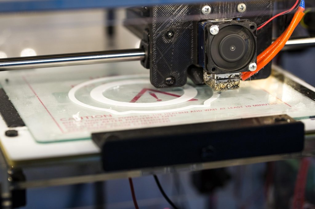
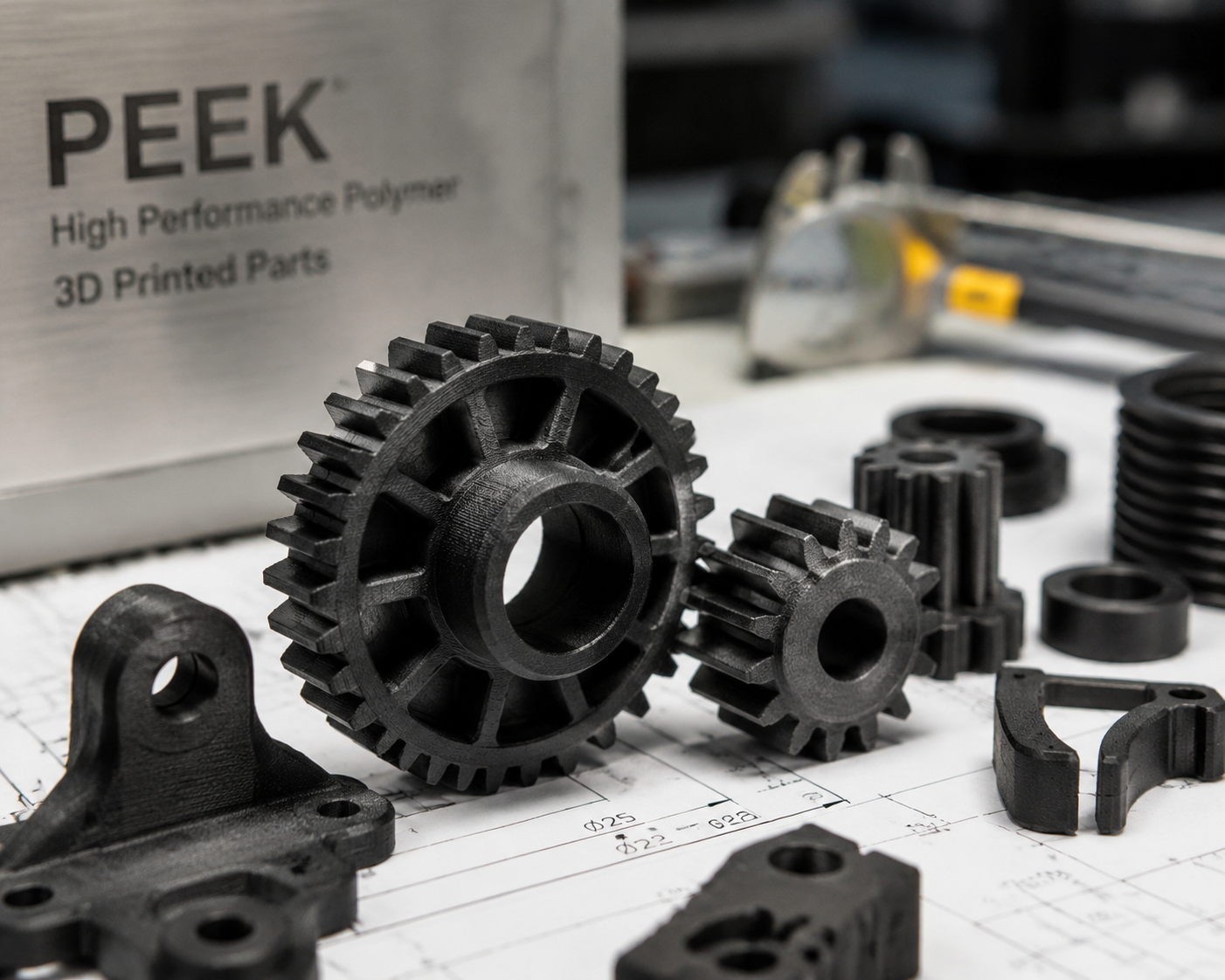
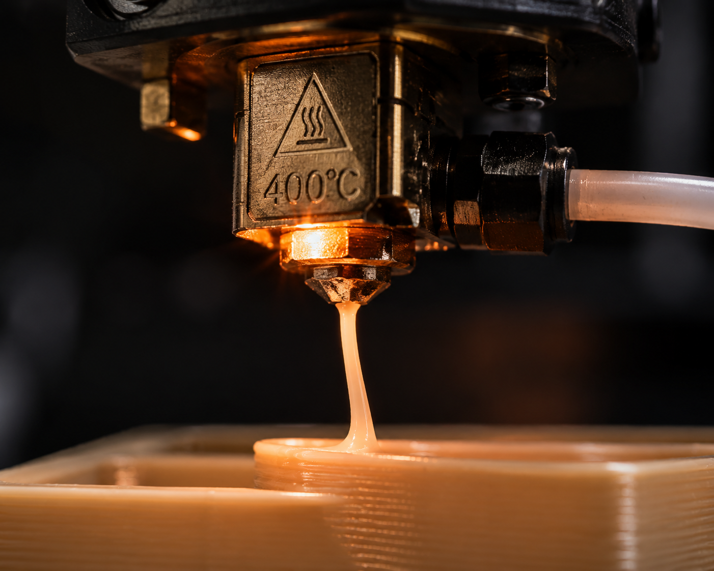
PEEK filament 3D printing only works reliably when the machine, dryer, and thermal environment are all built for it. PEEK (polyether ether ketone) sits at the top of the FDM material hierarchy. It is the polymer that engineers turn to when PEI (Ultem) is not quite enough and metal is too heavy, too expensive, or too slow to machine. With a continuous service temperature of 250°C, tensile strength exceeding 100 MPa, and chemical resistance that rivals fluoropolymers, PEEK enables 3D printed parts that genuinely replace machined metal components in aerospace, medical, and oil and gas applications.
This guide covers everything a professional user needs to know about printing PEEK: which machines can handle it, what temperatures and settings produce reliable parts, how to manage crystallinity for optimal mechanical properties, and when PEEK is — and is not — the right choice for your application. If you are still comparing hardware tiers first, our guide to the Las mejores impresoras 3D para materiales de ingeniería is the right companion page.
What Makes PEEK Different from Every Other 3D Printing Filament
PEEK belongs to the PAEK (polyaryletherketone) family of semi-crystalline thermoplastics. Its molecular structure — alternating ketone and ether linkages between aromatic rings — gives it a combination of properties unmatched by any amorphous thermoplastic used in 3D printing. The melting point of approximately 343°C is more than 100°C above polycarbonate and nearly 200°C above PETG. This is not an incremental step up in temperature capability; it is a different class of material entirely.
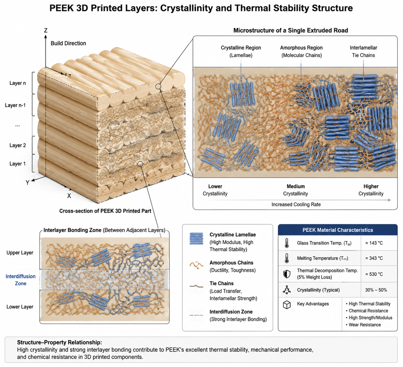
The semi-crystalline nature of PEEK is both its greatest asset and the primary challenge in printing it. Unlike amorphous polymers that simply soften and flow when heated, semi-crystalline PEEK undergoes a phase transition from ordered crystalline regions to disordered melt. When the extruded bead cools, those crystalline regions reform — but only if cooling is slow enough to allow polymer chains to organize. Rapid cooling produces amorphous PEEK with roughly 70 MPa tensile strength and poor chemical resistance. Controlled slow cooling produces crystalline PEEK with tensile strength above 100 MPa, excellent chemical resistance, and the full thermal performance the material is known for.
This crystallinity dynamic means that printing PEEK is not simply about reaching the right temperature — it is about managing the entire thermal history of the part from extrusion through final cooling. The printer, the environment, and the process parameters all matter.
Printer Requirements: Can Your Machine Print PEEK?
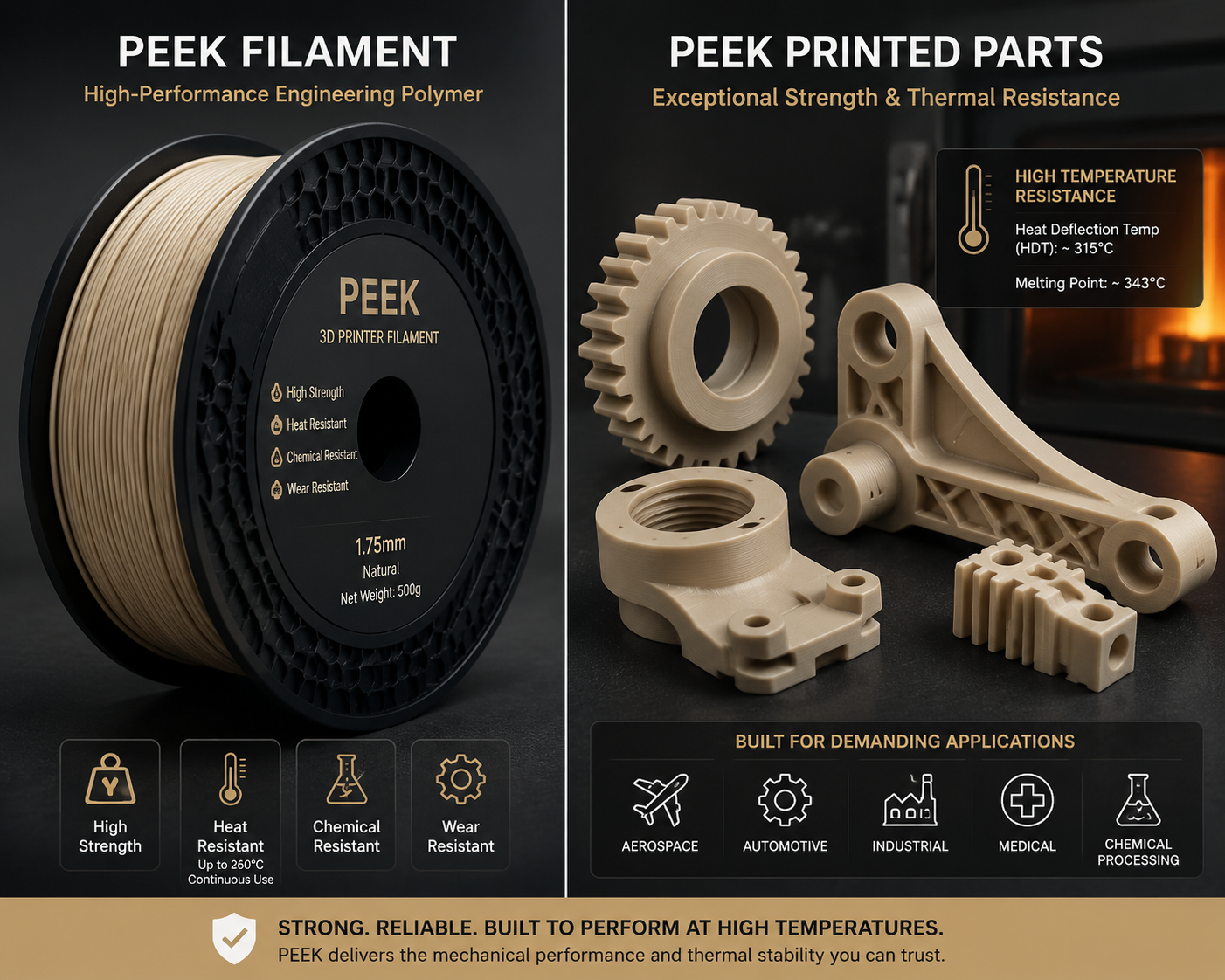
PEEK printing imposes hard requirements on every component of the printer. There are no compromises or workarounds — if any single requirement is not met, the printer simply cannot produce usable PEEK parts.
Hotend: 400°C Minimum, All-Metal Mandatory
The hotend must reach and hold at least 400°C, with 450°C preferred for printing at the upper end of PEEK’s processing window. This rules out any hotend with PTFE liners (PTFE decomposes above 260°C, releasing toxic fumes) and any hotend with aluminum heater blocks (aluminum softens significantly above 350°C). Copper, brass, or tool steel heater blocks with high-temperature thermistors or thermocouples are required. The nozzle should be hardened steel or a wear-resistant alloy — PEEK itself is not abrasive, but the high temperatures accelerate wear on brass nozzles.
The thermal break between the hotend and cold end becomes critical at these temperatures. A titanium or stainless steel heat break with active water cooling on the cold side is standard on commercial PEEK printers. Air-cooled heat breaks struggle to maintain a sharp thermal gradient at 400°C, leading to heat creep and jams.
Heated Chamber: 120-200°C, Actively Controlled
The chamber temperature is arguably more important for PEEK than the nozzle temperature. PEEK crystallizes optimally when the ambient temperature during printing is between 120°C and 200°C — well above what most enclosed printers can maintain. At chamber temperatures below 120°C, the printed part cools too quickly, producing predominantly amorphous PEEK with roughly 70% of optimal mechanical properties. At 180-200°C chamber temperature, crystallization proceeds during printing, producing parts that approach the properties of injection-molded PEEK directly off the build plate.
Commercial PEEK printers (Intamsys, 3DGence, Roboze, Apium) achieve these chamber temperatures with active heating elements, insulated enclosures, and often a secondary chamber heater independent of the bed. A printer that merely traps heat from the bed inside an enclosure will not reach the temperatures needed for proper PEEK crystallization — the bed alone cannot heat a full chamber volume to 150°C and above.
Heated Bed: 130-200°C
The bed must maintain 130-200°C throughout the print. Standard PCB heater beds with FR4 substrates degrade above 130°C. Aluminum beds with silicone heaters are standard for PEEK. Bed adhesion is challenging — PEEK warps aggressively, and standard print surfaces (PEI sheets, BuildTak) soften or degrade at these temperatures. PEI (Ultem) sheets are ironically the standard bed surface for PEEK printing, as pure PEI film bonded to the build plate provides a compatible interface that PEEK will adhere to when properly heated.
Filament Drying: Non-Negotiable
PEEK absorbs moisture from ambient air, though less aggressively than nylon. At processing temperatures of 400°C, even trace moisture hydrolyzes the polymer, reducing molecular weight and mechanical properties. PEEK filament must be dried at 120-150°C for 4-6 hours before printing and printed from an actively heated dry box that maintains 100-120°C. A passive desiccant dry box is insufficient — at room temperature, PEEK desorbs moisture too slowly for passive drying to be effective in a reasonable timeframe.
| Requisito | Minimum | Optimal | Notas |
|---|---|---|---|
| Temperatura de la boquilla | 380°C | 400-430°C | All-metal hotend only; PTFE = toxic failure |
| Temperatura de la cámara | 90°C | 150-200°C | Controls crystallinity; below 90°C = amorphous only |
| Temperatura de la cama | 130 °C | 160-200°C | PEI (Ultem) bed surface recommended |
| Filament Drying | 120°C / 4h | 150°C / 6h | Print from actively heated dry box (100-120°C) |
| Nozzle Material | Hardened Steel | Tool Steel / Ruby | Brass degrades at these temps |
| Printer Cost (Entry) | $5,000-8,000 | $15,000-30,000 | Desktop PEEK-capable machines start at ~$5K |
Print Settings for Optimal PEEK Parts
Temperature Window: Finding the Sweet Spot
The PEEK processing window is narrower than most users expect. At 370-380°C, PEEK flows but interlayer adhesion is poor because the extruded bead cannot adequately remelt the previous layer surface. At 420-440°C, flow is excellent but thermal degradation begins — the polymer chains start breaking down, producing a noticeable odor and reduced mechanical properties. The optimal range for most PEEK grades is 390-410°C, balancing sufficient melt fluidity for interlayer diffusion against thermal stability.
Temperature calibration for PEEK differs from conventional filaments. The standard temperature tower test does not capture the effect of chamber temperature on crystallinity. Instead, print small tensile bars at different nozzle and chamber temperature combinations, then test them mechanically and examine fracture surfaces. An amorphous PEEK tensile bar will neck and draw before fracture; a properly crystalline bar will be stiffer and stronger but more brittle. Both are valid — you are selecting the property balance your application needs.
Layer Height and Extrusion: Thinking in Crystal Domains
PEEK crystallizes in spherulites — spherical crystal domains that grow from nucleation points as the polymer cools. These spherulites are typically 10-50 microns in diameter, which imposes a practical constraint on layer height. Printing at layer heights below 0.1mm creates so many interfaces that the interlayer boundary becomes the dominant structural feature, reducing Z-direction strength. Layer heights of 0.15-0.25mm provide the best balance between resolution and interlayer strength. Some high-temperature printers use 0.3mm layers for purely structural parts where surface finish is secondary.
Extrusion width should be 120-150% of nozzle diameter to maximize the contact area between adjacent beads. On a 0.4mm nozzle, this means 0.48-0.60mm extrusion width. The wider bead has more thermal mass, stays molten longer, and creates a larger fusion zone with neighboring extrusions.
Print Speed: Slower Than You Think
PEEK should be printed at 20-40mm/s — significantly slower than even polycarbonate. At these speeds, the extruded bead has time to transfer heat to the previous layer and achieve sufficient interlayer polymer diffusion before the chamber temperature begins cooling the bead. Printing faster than 50mm/s with PEEK almost always produces weak interlayer bonding regardless of temperature, because the polymer simply does not spend enough time above its crystallization temperature at the interface.
A practical speed calibration: print a small cube at 20, 30, 40, and 50mm/s, then break each cube in a vise. The 20mm/s cube should break through the bulk material rather than along layer lines. If even the 20mm/s cube delaminates, your temperature or chamber heat is insufficient.
Annealing: Finishing What the Printer Started
Even with a 200°C chamber, printed PEEK may not achieve full crystallinity during the print. Annealing — a controlled post-print heat treatment — completes the crystallization process. The standard PEEK annealing cycle is: heat the printed part to 200°C at 1-2°C per minute, hold at 200°C for 2-4 hours (depending on part thickness), then cool to room temperature at 0.5-1°C per minute. This slow cooling is critical — rapid cooling freezes in amorphous regions and can induce thermal stresses that cause warping.
Annealing increases density by 1-3%, increases tensile strength by 10-20%, and dramatically improves chemical resistance. Parts that will see aggressive chemical environments (strong acids, steam, oilfield chemicals) should always be annealed. A simple density test — weighing the part in air and in water — can confirm whether annealing achieved full crystallinity.
PEEK Material Properties: Why Engineers Choose It
| Propiedad | Amorphous PEEK (As-Printed) | Crystalline PEEK (Annealed) | Injection-Molded PEEK |
|---|---|---|---|
| Resistencia a la tracción | 65-80 MPa | 90-105 MPa | 90-110 MPa |
| Módulo de flexión | 3,0-3,5 GPa | 3.8-4.2 GPa | 3.9-4.5 GPa |
| Continuous Service Temp | 180 °C | 250 °C | 250-260°C |
| Transición vítrea (Tg) | 143°C | 143°C | 143°C |
| Melting Point (Tm) | 343 °C | 343 °C | 343 °C |
| Densidad | 1.26 g/cm³ | 1.30-1.32 g/cm³ | 1.30-1.32 g/cm³ |
| Resistencia química | Bien | Excelente | Excelente |
| Inflamabilidad | V-0 (0.8mm) | V-0 (0.8mm) | V-0 (0.8mm) |
PEEK Filament Grades and Variants
Pure unfilled PEEK is not the only option. Several filled and modified grades address specific application requirements, and most are available as 3D printing filament from specialty manufacturers.
Unfilled PEEK (Natural) is the standard grade, appearing as an opaque tan or light brown polymer. It provides the best combination of strength, toughness, and chemical resistance for general-purpose applications. Natural PEEK is the default choice unless a specific filled grade requirement exists.
Carbon Fiber Reinforced PEEK (CF-PEEK) contains 10-30% carbon fiber by weight. The fibers increase stiffness (flexural modulus rises to 12-20 GPa, a 3-5x improvement over unfilled), reduce thermal expansion to near-aluminum levels, and improve wear resistance dramatically. The tradeoff is increased brittleness, abrasive wear on nozzles, and anisotropic mechanical properties — parts are strongest in the print direction where fibers align with the extrusion path. CF-PEEK requires hardened steel or ruby-tipped nozzles and typically runs at 400-430°C.
Glass Fiber Reinforced PEEK (GF-PEEK) uses glass fibers at 20-30% loading. The mechanical improvement is less dramatic than carbon fiber (flexural modulus 6-9 GPa) but the material is electrically insulating, which matters for electronic and semiconductor applications. GF-PEEK also costs significantly less than CF-PEEK.
Bearing-Grade PEEK incorporates solid lubricants — typically graphite, PTFE, or both — to reduce friction and improve wear life. These grades are used for printed bearings, bushings, and wear surfaces in applications where external lubrication is impractical. The coefficient of friction against steel can drop below 0.15 with these formulations.
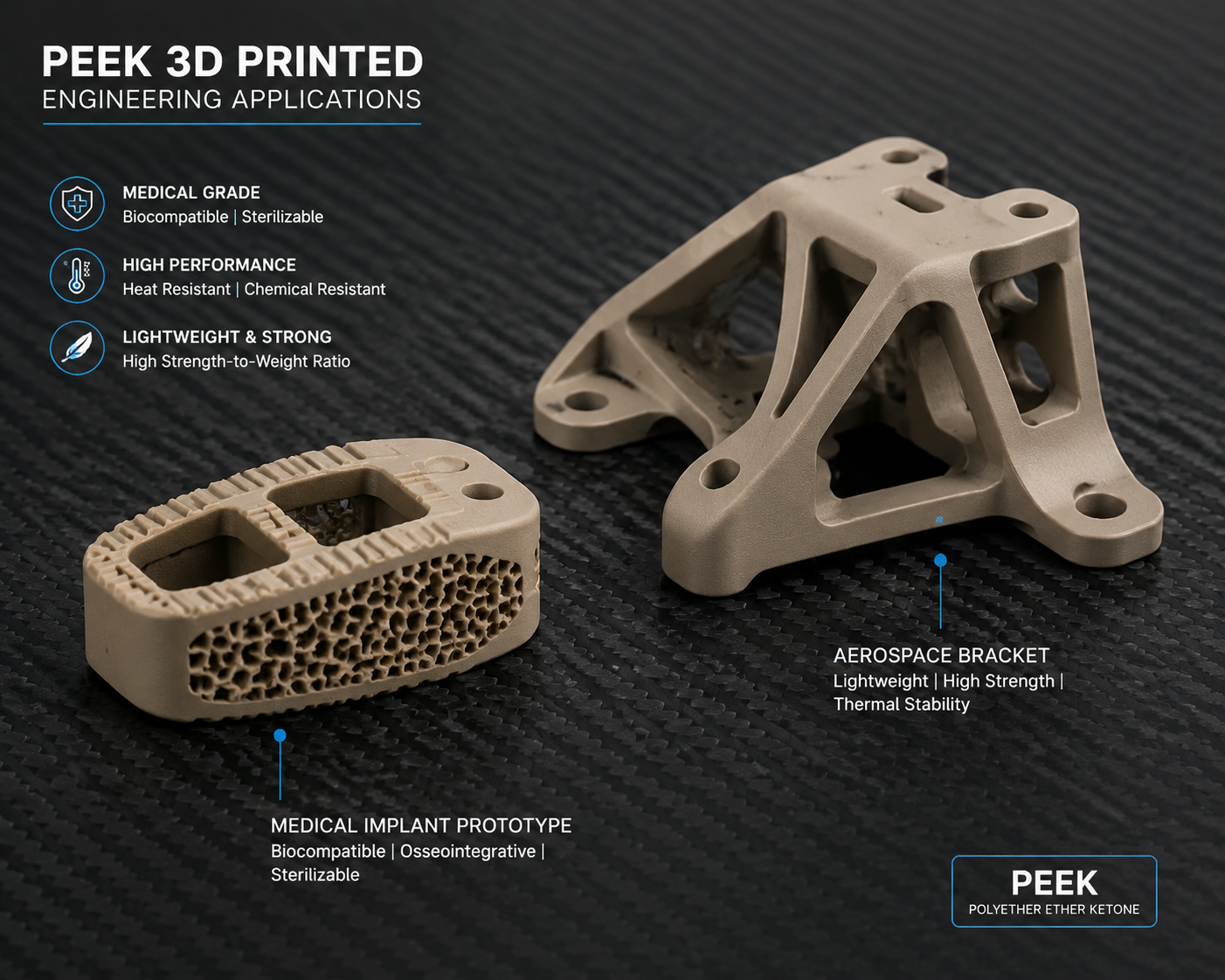
Medical-Grade PEEK is manufactured under ISO 13485 quality systems with documented biocompatibility testing. Implantable grades (such as Invibio PEEK-OPTIMA) meet USP Class VI and ISO 10993 requirements for long-term implantation. The 3D printing of implantable PEEK devices is an active area of regulatory development — printed spinal cages and cranial implants have received regulatory clearance in multiple jurisdictions.
Applications: Where PEEK 3D Printing Delivers Value
Aeroespacial
PEEK’s combination of high strength-to-weight ratio, inherent flame retardancy (UL 94 V-0 at 0.8mm), and low smoke and toxicity emissions makes it the default polymer for aircraft interior components, ducting, brackets, and electrical insulators. 3D printed PEEK enables rapid iteration of these components during development and cost-effective production of low-volume spares. A printed PEEK bracket weighing 50 grams can replace a machined aluminum bracket weighing 200 grams in non-structural applications, reducing aircraft weight and fuel consumption over the component’s service life.
Productos sanitarios
PEEK is radiolucent — it does not appear on X-rays — making it ideal for surgical instruments and implant trials where the device must not obscure the surgeon’s view of anatomy. 3D printed PEEK patient-specific surgical guides, trial implants, and custom instrumentation are now routine in orthopedic and spinal surgery. The ability to print a custom cutting guide from a patient’s CT scan data and have it in the operating room within 48 hours transforms surgical planning workflows.
Petróleo y gas
Downhole tooling, seals, and electrical connectors in the oilfield see temperatures up to 200°C, pressures exceeding 100 MPa, and aggressive chemical environments including hydrogen sulfide, hydrochloric acid, and supercritical carbon dioxide. PEEK is one of the few polymers that survives these conditions, and 3D printing enables complex seal geometries that are difficult or impossible to machine. A printed PEEK seal that would require 5-axis CNC machining and 8-week lead time can be printed overnight.
Semiconductor Manufacturing
PEEK’s combination of high purity, low outgassing, and tolerance for aggressive cleaning chemicals makes it the material of choice for wafer handling components, chemical delivery system parts, and test sockets. 3D printed PEEK enables rapid turnaround on custom wafer fixtures and test jigs that would otherwise require weeks of machining. GF-PEEK is particularly valuable here for its electrical insulation properties combined with mechanical stability. If your end use may shift from printed validation to molded production, our PEEK injection molding guide is the next process reference to review.
Automotive and Motorsport
Under-hood components, especially in motorsport where service intervals are short and performance is everything, benefit from 3D printed PEEK. Intake components, sensor housings, and fluid connectors that must survive 150-200°C continuous exposure and resist hot oil, coolant, and fuel are within PEEK’s capability envelope. CF-PEEK is preferred for structural brackets where stiffness matters.
PEEK vs PEKK vs PEI (Ultem): Choosing the Right High-Temperature Material
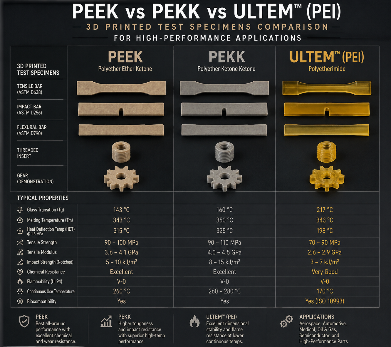
PEEK is the best-known PAEK polymer, but it is not the only one. PEKK (polyetherketoneketone) offers a higher glass transition temperature (approximately 160°C vs 143°C for PEEK) and faster crystallization kinetics, making it somewhat easier to print with good crystallinity. PEI (polyetherimide, sold as Ultem) prints at lower temperatures (350-380°C nozzle, 130-160°C chamber) and costs approximately half what PEEK does, with a continuous service temperature of 170-180°C. For users stepping up from mid-tier engineering materials first, our Guía de filamentos para PC helps frame the gap between polycarbonate workflows and true PAEK-class printing.
The decision tree is straightforward: if 170°C and PEI-level chemical resistance are sufficient, use Ultem and save significantly on both material cost and printer requirements. If the application genuinely requires 250°C service temperature, aggressive chemical resistance, or medical implant compatibility, PEEK is the answer. PEKK occupies a middle ground for applications that push past PEI’s thermal limits but do not quite need PEEK’s full capability.
Practical Constraints: What PEEK Cannot Do
PEEK is not a universal solution. Its limitations are as important to understand as its capabilities. The material cost — $300-800/kg for filament-grade PEEK — makes failed prints expensive. A failed 100-gram print represents $30-80 in material alone, plus printer time and energy. This reality means that design and process validation should be done in a cheaper material (PC or even PLA for fit-checking) before committing to PEEK.
Support material for PEEK is limited. Unlike PLA or PETG where dedicated breakaway or soluble supports are available, PEEK supports must be printed in PEEK itself. This means support removal is mechanical — cutting, grinding, and filing — and support interfaces will leave surface marks that must be post-processed. Designs that require extensive soluble supports are not good candidates for PEEK printing.
Color options are restricted. PEEK in its natural state is tan to light brown. Carbon-filled grades are black. Beyond these, color options are essentially nonexistent because pigments that survive 400°C processing are rare and expensive. If appearance matters, PEEK parts are typically post-processed (painted, coated) rather than printed in color.
Size is limited by chamber heating. PEEK printers with 200°C chambers are typically limited to build volumes of 200x200x200mm or smaller because heating larger volumes to 200°C uniformly requires kilowatts of power and substantial insulation. Large PEEK parts are generally not practical with current desktop and benchtop printer technology.
Getting Started with PEEK: A Practical Roadmap
If you are considering PEEK for the first time, the most common and costly mistake is starting with a complex functional part. The learning curve is steep, and each failed print at $300-800/kg is a meaningful line item. The recommended approach is:
First, verify that your application genuinely needs PEEK. If Ultem (PEI) at half the cost and lower printer requirements will do the job, start there. Many applications that specify PEEK do so because the engineer knows PEEK from injection molding experience, not because the application’s actual thermal or chemical requirements demand it.
Second, run the complete thermal calibration sequence: print small tensile bars at nozzle temperatures from 380°C to 420°C in 10°C increments, at chamber temperatures of 120°C, 150°C, and 180°C. Test these bars for tensile strength and interlayer adhesion. This matrix — not a generic profile from a filament datasheet — determines your process window for your specific printer, filament batch, and part geometry.
Third, design for PEEK’s processing constraints. Avoid overhangs that require supports. Include generous fillets on all internal corners to reduce stress concentrations that cause warping. Design the part so that the primary load direction aligns with the print direction. And always print a small witness coupon alongside the part that can be destructively tested to verify mechanical properties.
Fourth, invest in post-processing capability. An annealing oven capable of holding 200°C with controlled ramp rates is as essential as the printer itself for achieving full PEEK properties. A bench vise and hammer for destructive testing of witness coupons provide the fastest and most honest quality control feedback.
PEEK 3D printing is not for everyone. But for the right applications — where the combination of 250°C thermal capability, chemical inertness, and biocompatibility justifies the investment — it delivers capabilities that no other FDM material can approach. The gap between a 3D printed PEEK part and a machined PEEK part narrows with every generation of printer hardware and process knowledge.
Preguntas frecuentes
Can you print PEEK on a modified Ender 3 or similar budget printer?
No. This is the most common PEEK-related question and the answer is unambiguous. Even with a hotend upgrade, enclosure, and firmware modifications, an Ender 3-class printer cannot print PEEK successfully. The reasons: (1) the stock motion system and frame are not designed for 60°C ambient, let alone 120-200°C — belts stretch, stepper motors overheat, and electronics fail; (2) PCB heated beds cannot reach or sustain 130-200°C; (3) the enclosure cannot maintain uniform chamber temperature at the required levels; (4) PTFE-lined Bowden tubes, if present, will decompose and release toxic fumes at the temperatures required. PEEK printing requires a purpose-built high-temperature printer. Attempting it on a modified budget printer is both unlikely to succeed and potentially hazardous.
How much does PEEK filament cost?
Standard unfilled PEEK filament ranges from $300-500/kg from established manufacturers (3DXTech, Essentium, Victrex). Carbon fiber reinforced PEEK costs $500-800/kg. Medical-grade PEEK with full biocompatibility documentation can exceed $800/kg. These prices reflect both the high cost of PEEK resin and the specialized manufacturing required to produce consistent-diameter filament that prints reliably at 400°C. Small spools (250g) are available for evaluation and small-part production at a per-kg premium.
What is the difference between amorphous and crystalline PEEK in practical terms?
Amorphous PEEK (rapidly cooled from melt) has approximately 70 MPa tensile strength, is translucent amber in color, has moderate chemical resistance (will swell and crack in strong solvents), and loses mechanical properties above 180°C. Crystalline PEEK (slowly cooled or annealed) has 90-105 MPa tensile strength, is opaque tan to brown, has excellent chemical resistance (insoluble in all common solvents below 200°C), and maintains properties to 250°C. The density difference (1.26 vs 1.30 g/cm³) provides a simple quality control check. Most applications require crystalline PEEK for its full performance envelope.
Is 3D printed PEEK as strong as machined PEEK?
Properly printed and annealed PEEK can achieve 85-95% of machined PEEK’s tensile strength and 70-85% of its fatigue life. The Z-direction (interlayer) strength is typically 30-50% lower than X-Y plane strength, which is the primary mechanical limitation. For applications where the primary load aligns with the print layers, printed PEEK is structurally competitive with machined PEEK. For applications requiring isotropic strength — equal properties in all directions — machined PEEK from compression-molded stock remains superior, though the gap is narrowing with each generation of printer and process improvement.