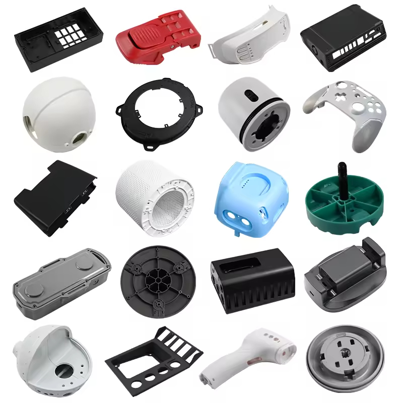
1. Introducción: Por qué son importantes las nervaduras y los salientes en el moldeo por inyección
En el moldeo por inyección, los diseñadores de piezas se enfrentan constantemente a un reto fundamental: lograr la resistencia estructural rigidez y resistencia manteniendo al mismo tiempo un espesor uniforme de las paredes. El simple hecho de aumentar el espesor de las paredes aumenta el coste del material, alarga la duración del ciclo e introduce deformaciones, marcas de hundimiento y huecos internos. Las nervaduras y los salientes son la solución.
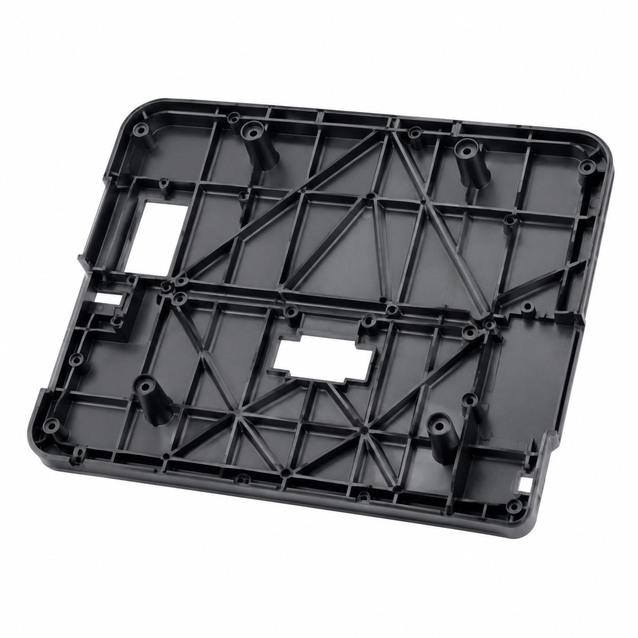
Costillas Son salientes delgados, similares a paredes, que aumentan considerablemente la rigidez a la flexión sin incrementar proporcionalmente el espesor de la pared. Una nervadura bien diseñada puede duplicar el momento de inercia de una pieza, al tiempo que solo añade entre un 10 y un 20% al volumen de material.
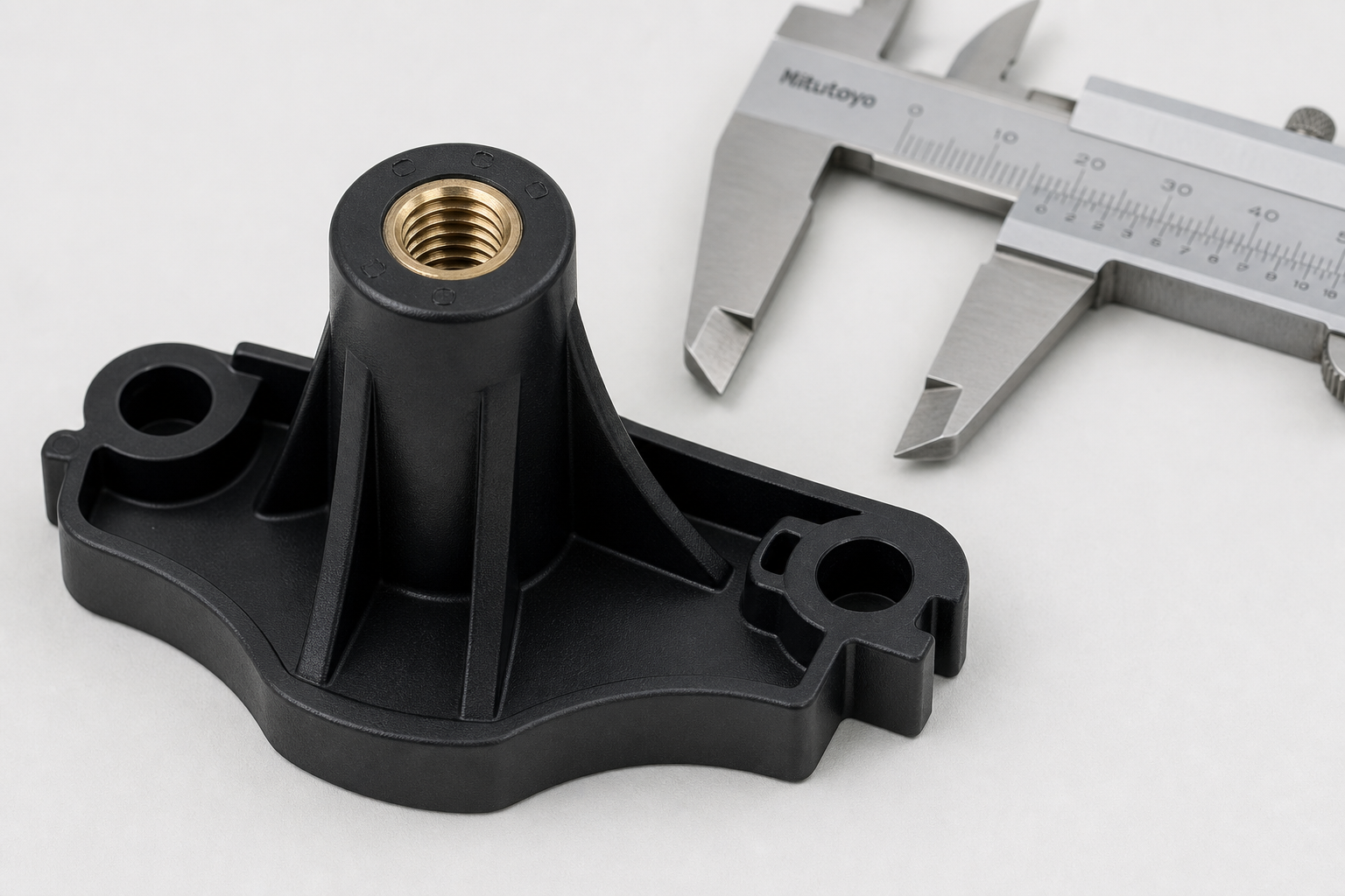
Jefes son salientes cilíndricos diseñados para acoplarse a tornillos autorroscantes, insertos roscados o pasadores de posicionamiento. Concentran fuerzas de montaje y deben diseñarse con cuidado para evitar marcas de hundimiento en la superficie estética opuesta.
Esta guía trata sobre el normas de diseño contrastadas, tablas de dimensiones y errores habituales para las nervaduras y los salientes de los componentes de plástico moldeados por inyección. Tanto si diseñas carcasas para productos electrónicos de consumo, piezas para el interior de vehículos o carcasas para dispositivos médicos, estos principios se aplican de forma universal.
2. Normas y buenas prácticas para el diseño de nervaduras
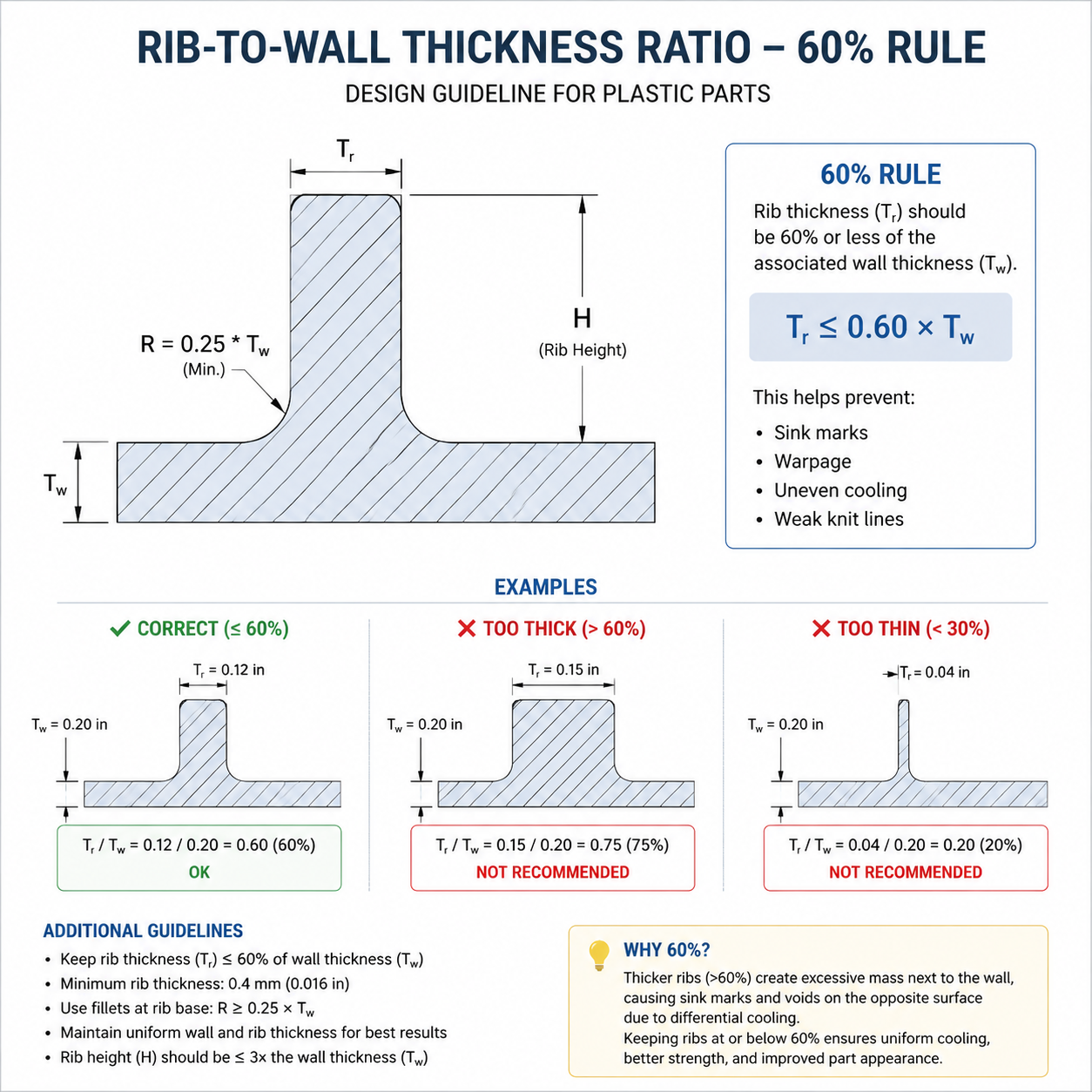
2.1 Espesor de las nervaduras
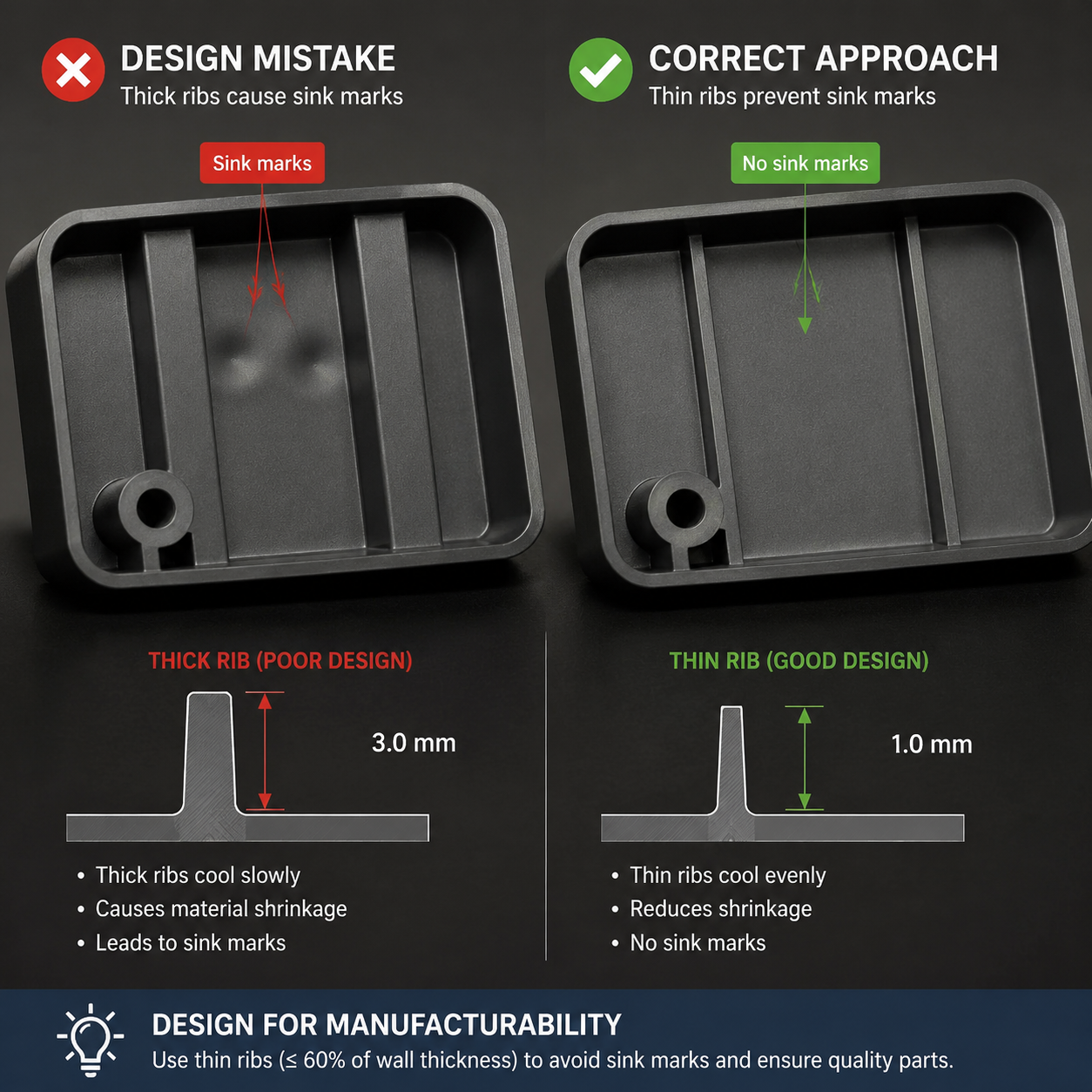
La regla más importante de todas: El espesor de la nervadura no debe superar el 60% del espesor nominal de la pared. en la base de la costilla.
| Espesor nominal de la pared (mm) | Espesor máximo de la base de la nervadura (mm) |
|---|---|
| 1.0 | 0.60 |
| 1.5 | 0.90 |
| 2.0 | 1.20 |
| 2.5 | 1.50 |
| 3.0 | 1.80 |
| 3.5 | 2.10 |
| 4.0 | 2.40 |
Si se incumple la regla 60%, la base de la nervadura se enfría más lentamente que la pared adyacente, lo que da lugar a un marca de hundimiento visible en la superficie opuesta. Para Superficies cosméticas de clase A, limitar el espesor de las nervaduras a un valor comprendido entre 40 y 50% del espesor de la pared, para disponer de un margen de seguridad adicional.
2.2 Altura de la nervadura
La altura máxima de las nervaduras no debe superar 3 veces el grosor de la base de la costilla. Las nervaduras altas y delgadas son difíciles de rellenar, propensas a que se produzcan rellenos insuficientes y difíciles de desmoldar. En el caso de las nervaduras estructurales fabricadas con termoplásticos de ingeniería (PA, PBT, POM), los límites prácticos son:
- Costillas estándar: Altura ≤ 3 × espesor de la nervadura
- Costillas profundas: Altura ≤ 5 × espesor de la nervadura (requiere una base más ancha o refuerzos)
- Motivos de nervaduras cruzadas: Altura ≤ 5 × espesor de la nervadura (las intersecciones se refuerzan entre sí)
2.3 Ángulo de inclinación
Cada costilla debe incluir un ángulo de calado mínimo de 0,5 grados por cada lado. Un ángulo de desmoldeo insuficiente genera una fuerza de expulsión excesiva, lo que podría dañar la costilla o la pieza. Ángulo de desmoldeo recomendado según el material:
| Tipo de material | Calado mínimo (por cada lado) | Corriente recomendada (por lado) |
|---|---|---|
| Sin relleno (PP, PE, ABS) | 0,5° | 1,0° |
| Con relleno de vidrio (PA6-GF30, PBT-GF30) | 1,0° | 1,5° |
| High-temperature (PPS, PEEK) | 1,0° | 2.0° |
| Textured surfaces (any material) | 1.5° per 0.025 mm texture depth | — |
2.4 Rib Spacing
Adjacent ribs should be spaced at least 2 times the nominal wall thickness apart. Closer spacing creates thick material zones that cool unevenly, causing sink marks and internal stress concentrations. For parallel rib arrays, maintain a minimum center-to-center distance of 2.5–3.0 times the nominal wall to ensure uniform cooling.
3. Boss Design Rules
3.1 Boss Outer Diameter
The boss outer diameter should be approximately 2 times the screw diameter for self-tapping screws. This provides sufficient material engagement while minimizing sink mark risk.
| Screw Size | Nominal Diameter (mm) | Boss OD (mm) | Pilot Hole (mm) | Wall Thickness (mm) | Min. Height (mm) |
|---|---|---|---|---|---|
| M2 | 2.0 | 4.0 | 1.6 | 1.2 | 4.0 |
| M2.5 | 2.5 | 5.0 | 2.0 | 1.5 | 5.0 |
| M3 | 3.0 | 6.0 | 2.4 | 1.8 | 6.0 |
| M4 | 4.0 | 8.0 | 3.2 | 2.4 | 8.0 |
| M5 | 5.0 | 10.0 | 4.0 | 3.0 | 10.0 |
| M6 | 6.0 | 12.0 | 4.8 | 3.6 | 12.0 |
| M8 | 8.0 | 16.0 | 6.5 | 4.75 | 16.0 |
Nota: Boss wall thickness should not exceed 60% of the nominal part wall thickness. If this constraint cannot be met (e.g., large screw on thin wall), use gussets or ribs to reinforce the boss externally rather than thickening the boss wall.
3.2 Boss Height and Aspect Ratio
Boss height should typically not exceed 3 times the boss outer diameter. Tall, unsupported bosses are prone to deflection during screw insertion and may fracture. For taller bosses, use:
- Gussets: Triangular reinforcements connecting boss to base wall
- Rib connections: Tie boss to adjacent structural ribs
- Counterbore design: Recess the screw head to reduce effective height
3.3 Draft Angle for Bosses
Both the inner core and outer surface of bosses require draft. The inner core (core pin) should have a minimum draft of 0.5 degrees. The outer surface can have slightly less draft if the boss is short, but 0.5 degrees minimum is strongly recommended. For bosses taller than 10 mm, increase the core pin draft to 1.0 degrees to ensure reliable ejection without drag marks.
4. Common Design Mistakes and Solutions
4.1 Thick Ribs Causing Sink Marks
Problem: Rib thickness exceeding 60% of the nominal wall creates a localized mass of material that cools slower than surrounding areas. As the thicker section shrinks during cooling, it pulls the adjacent surface inward, creating a marca de hundimiento visible on the cosmetic surface.
Solution: Reduce rib thickness to ≤60% (preferably 50%) of the nominal wall. If structural stiffness is insufficient, use multiple thinner ribs or cross-rib patterns instead of one thick rib. For parts with Class A surfaces, apply the 40% rule and add surface texturing to mask any minor sink.
4.2 Tall Bosses Causing Short Shots
Problem: Bosses taller than 3× their diameter create a long, narrow flow path. The melt front cools before reaching the top of the boss, resulting in a short shot or incomplete filling at the boss tip.
Solution: Keep boss height within the 3× diameter limit. For unavoidable tall bosses, increase the gate size, raise melt temperature, or add a vent pin at the boss tip to allow trapped air to escape. Mold flow analysis can predict fill patterns and confirm whether a tall boss will fill completely under your processing parameters.
4.3 Insufficient Draft Causing Ejection Issues
Problem: Ribs and bosses with less than 0.5 degrees of draft lock onto the mold core during ejection. This causes drag marks, stress whitening, or even part breakage when the ejector pins push the part off the core.
Solution: Apply minimum 0.5 degree draft on all vertical surfaces, increasing to 1.0–1.5 degrees for glass-filled materials and textured surfaces. Always specify draft angle on the 2D drawing, not just in the 3D model, so the mold maker cannot overlook it. Verify draft angles in your CAD software before releasing the design to tooling.
4.4 Missing Corner Radius at Rib-Base Intersection
Problem: A sharp corner where the rib meets the base wall creates a stress concentration and a flow restriction. The sharp internal corner acts as a notch, significantly reducing fatigue life and increasing the risk of crack initiation.
Solution: Add a minimum radius of 0.25–0.5 mm at the rib-to-wall intersection. The radius reduces stress concentration and improves melt flow. For parts subject to cyclic loading or impact, use 0.5–0.75 mm. This small geometry change has negligible impact on tooling cost but dramatically improves part durability.
5. Gusset and Corner Reinforcement Design
5.1 Gusset Plates for Boss Reinforcement
Gussets are triangular support plates that connect a boss to the part base wall. They dramatically increase lateral stiffness and bending resistance at minimal material cost. Design rules for gussets:
- Gusset thickness: Same as or slightly less than rib thickness (≤60% of nominal wall)
- Gusset height: 50–75% of boss height
- Gusset width at base: 1.5–2.0 × boss outer diameter
- Number of gussets: Typically 3–4 equally spaced around the boss circumference
- Draft: Same draft angle as the boss or rib
5.2 Corner Reinforcement
Box-shaped plastic housings benefit significantly from corner ribs. A diagonal rib across an internal corner increases torsional stiffness by 40–60% with minimal material addition. Design guidelines:
- Rib position: Centered at 45 degrees across the corner
- Rib thickness: Same as standard rib rules (≤60% of wall)
- Rib depth: 2–3 × wall thickness into the part cavity
- Rib length: Extend at least 3–5 × wall thickness along each corner face
5.3 Cross-Rib and Honeycomb Patterns
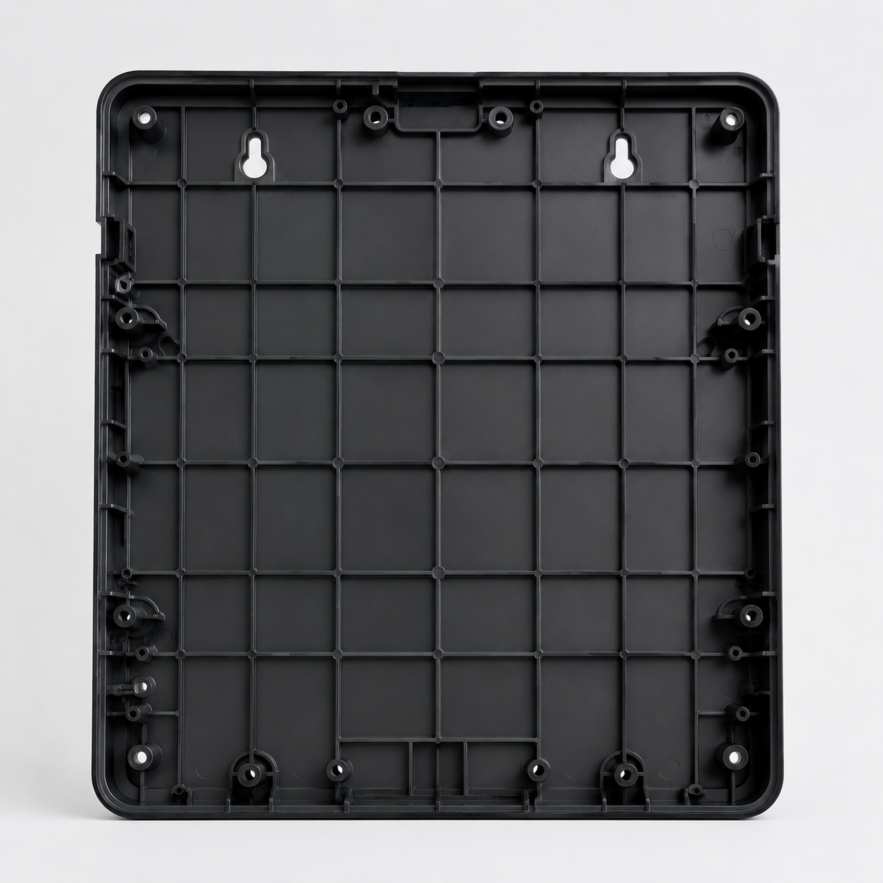
For large flat panels, a grid or honeycomb rib pattern provides excellent stiffness-to-weight ratio. The intersecting ribs support each other against buckling, allowing greater rib height (up to 5× rib thickness). Honeycomb patterns are particularly effective because they distribute loads evenly across all six sides of each cell. When designing rib grids:
- Cell size: 5–10 × nominal wall thickness
- Rib intersection radius: 0.5–1.0 mm minimum to avoid stress risers at nodes
- Draft: Same 0.5–1.0 degree rule applies to all grid ribs
6. Comprehensive Design Table: Recommended Dimensions by Screw Size
The following table summarizes all critical boss dimensions for self-tapping screw applications from M2 through M8. Use these as starting values for your design, adjusting for specific material properties and application requirements.
| Parámetro | M2 | M2.5 | M3 | M4 | M5 | M6 | M8 |
|---|---|---|---|---|---|---|---|
| Screw Nominal Diameter | 2.0 mm | 2.5 mm | 3.0 mm | 4.0 mm | 5.0 mm | 6.0 mm | 8.0 mm |
| Boss Outer Diameter | 4.0 mm | 5.0 mm | 6.0 mm | 8.0 mm | 10.0 mm | 12.0 mm | 16.0 mm |
| Pilot Hole (Self-Tapping) | 1.6 mm | 2.0 mm | 2.4 mm | 3.2 mm | 4.0 mm | 4.8 mm | 6.5 mm |
| Boss Wall Thickness | 1.2 mm | 1.5 mm | 1.8 mm | 2.4 mm | 3.0 mm | 3.6 mm | 4.75 mm |
| Minimum Boss Height | 4.0 mm | 5.0 mm | 6.0 mm | 8.0 mm | 10.0 mm | 12.0 mm | 16.0 mm |
| Gusset Thickness | 1,0 mm | 1.2 mm | 1.4 mm | 1.8 mm | 2.2 mm | 2.6 mm | 3.4 mm |
| Recommended Screw Engagement | 3.0 mm | 3.8 mm | 4.5 mm | 6.0 mm | 7.5 mm | 9.0 mm | 12.0 mm |
| Minimum Nominal Wall for Boss | 2.0 mm | 2.5 mm | 3.0 mm | 4.0 mm | 5.0 mm | 6.0 mm | 8.0 mm |
7. Frequently Asked Questions
¿Cuál es el espesor mínimo absoluto de las nervaduras que puedo utilizar en el moldeo por inyección?
The practical minimum rib thickness depends on the material flow characteristics and mold filling capabilities. For most unfilled thermoplastics (ABS, PC, PP), the minimum is approximately 0.5–0.6 mm at the rib tip. Below this, melt flow hesitation occurs — the material prefers to fill the thicker main wall rather than the thin rib. For glass-filled materials, the minimum increases to 0.8–1.0 mm due to higher viscosity. Always consult your molder’s mold flow analysis to confirm fillability before finalizing thin ribs. A useful rule of thumb: the rib tip thickness should never be less than 40% of the maximum rib base thickness to maintain a continuous flow path.
¿Cuándo debería utilizar nervaduras en lugar de limitarme a aumentar el grosor de la pared?
Use ribs instead of thickening walls whenever stiffness is the design requirement rather than raw strength. Ribs increase the moment of inertia exponentially with height (I = bh³/12), meaning a rib 3× wall thickness adds approximately 27× the bending stiffness of the base wall — with only a fraction of the material that would be needed to thicken the entire wall. Thicken the wall only when: (1) the part experiences uniform tensile or compressive loads rather than bending, (2) the part requires resistencia al impacto distributed across the entire surface, or (3) the aesthetic surface cannot tolerate any risk of sink marks from ribs on the opposite side. Even in these cases, consider reinforcing the thick section with carefully designed ribs to avoid exceeding 4–5 mm wall thickness, beyond which cycle time and warpage become severe problems.
¿Cómo debería diseñar una cabeza para tornillos autorroscantes en plástico?
For self-tapping screws in thermoplastics, three design parameters are critical: pilot hole diameter, boss wall thickness, and engagement length. The pilot hole should be 75–80% of the screw nominal diameter for most materials (e.g., 2.4 mm for an M3 screw). Boss wall thickness must be at least 40% of the screw diameter but not exceed 60% of the part nominal wall. The engagement length (screw penetration depth) should be 2.0–2.5× the screw diameter for reliable thread stripping resistance. For example, an M3 self-tapping screw requires a boss with 6 mm OD, 2.4 mm pilot hole, and minimum 6–7.5 mm engagement depth. Always specify the pilot hole diameter on the molding drawing — never rely on the molder to drill holes, as molded-in pilot holes are far more accurate and cost-effective than secondary drilling operations. Consider using threaded brass inserts when repeated assembly/disassembly is expected, as self-tapping screws lose holding strength after 3–5 re-insertions in most plastics.
¿Cómo puedo evitar que las costillas se hundan sin perder rigidez?
Avoiding sink marks on ribs requires a multi-pronged approach that addresses the root cause: localized mass concentration cooling slower than surrounding areas. Key strategies include: (1) Reduce rib thickness to 40–50% of nominal wall — the most direct solution, even if it means using more ribs to compensate for lost stiffness. (2) Add a radius at the rib-base intersection (0.25–0.5 mm) to smooth the thermal transition zone. (3) Use gas-assisted injection molding for thick ribs — the gas core hollows out the rib, eliminating the mass concentration entirely. (4) Texture the opposite surface — a light texture (MT-11000 or finer) masks minor sink marks visually. (5) Relocate the rib pattern to non-cosmetic areas if surface quality is critical. (6) Optimize packing pressure and hold time — a properly packed part shrinks less, reducing sink severity. For Class A surfaces (automotive exterior, consumer electronics visible faces), the 40% rule plus texturing is the proven industry standard. If even that is insufficient, consider a two-shot overmolding process where a soft-touch TPE skin covers the sink-prone surface.
Lecturas relacionadas
- Guía de diseño del espesor de las paredes en el moldeo por inyección
- Threaded Inserts for Plastic Parts: Design and Installation
- Plastic Part Tolerances and Molding Standards
Request a Rib and Boss DFM Review
Upload the drawing below for a manufacturability review, or see our nylon injection molding service.